
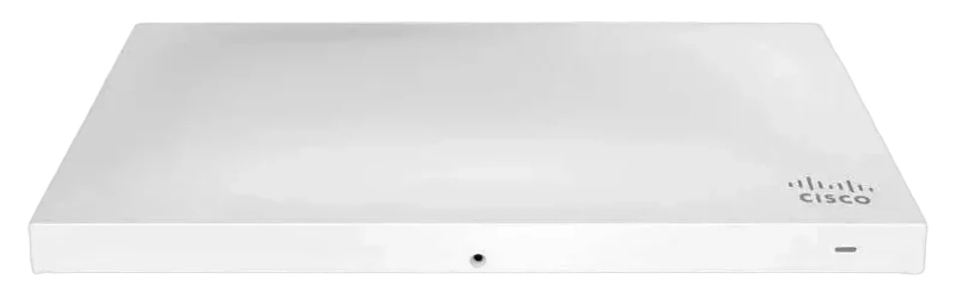
The Cisco Meraki MR53 is a cloud-managed 4×4:4 802.11ac Wave 2 access point with concurrent 2.4 GHz and 5 GHz client radios, 80 MHz channel support, MU-MIMO, a dedicated wireless security and RF analytics radio, and an integrated Bluetooth Low Energy radio.
It is designed for enterprise WLAN deployments in offices, schools, hospitals, retail locations, hotels, and other environments requiring high client density, centralized management, wireless security monitoring, and support for voice, video, and application-intensive traffic.
MR53 Product Positioning
The MR53 combines four concurrently operating radios:
- 2.4 GHz 802.11b/g/n client access radio
- 5 GHz 802.11a/n/ac client access radio
- Dual-band WIDS/WIPS, spectrum analysis, and location analytics radio
- 2.4 GHz Bluetooth Low Energy radio for Beacon and BLE scanning
The two client access radios provide a maximum aggregate frame rate of up to 2.5 Gbps. The published radio capability is up to 1,733 Mbps on 5 GHz and up to 800 Mbps on 2.4 GHz. These figures represent maximum over-the-air data frame capability of the radio chipset and may exceed data rates permitted by IEEE 802.11ac-compliant operation. They should not be used as guaranteed application throughput.
The MR53 is best suited to deployments where the design requires:
- High-density 802.11ac Wave 2 client access
- Four spatial streams and MU-MIMO
- Dedicated wireless intrusion detection and prevention
- Continuous spectrum monitoring without taking a client radio offline
- Bluetooth Low Energy beaconing and scanning
- Cloud-based configuration and monitoring
- Layer 7 traffic classification and shaping
- Fast Layer 2 and Layer 3 mobility
- Centralized deployment across distributed locations
MR53 Radio and Wireless Architecture
Client access radios
The 2.4 GHz radio supports 802.11b/g/n operation, 40 MHz channels for 802.11n, and up to four spatial streams. The 5 GHz radio supports 802.11a/n/ac operation, including 20 MHz, 40 MHz, and 80 MHz channels.
Both client radios support:
- 4×4 MIMO
- Four spatial streams
- SU-MIMO
- MU-MIMO
- Maximal Ratio Combining
- Transmit beamforming
- Packet aggregation
- Up to 256-QAM on both bands
The 5 GHz radio is the primary capacity band for high-density designs because it supports 80 MHz 802.11ac channels and provides the higher published maximum frame rate. The 2.4 GHz radio remains useful for legacy clients, IoT devices, and devices limited to the lower frequency band, but its channel availability and interference environment must be assessed during site design.
Dedicated security and RF radio
The third radio operates across 2.4 GHz and 5 GHz for continuous WIDS/WIPS, spectrum analysis, RF monitoring, and location analytics. It scans the environment independently of the client-serving radios.
This architecture avoids the operational compromise found in designs where a client-serving radio must periodically leave service to perform scanning. The MR53 can monitor for rogue access points, characterize RF interference, support automated rogue AP containment through Air Marshal, and collect RF data while continuing to serve wireless clients.
The Meraki cloud uses RF information collected by the dedicated radio to assist with channel selection, transmit power, and client connection optimization. This reduces the need for manual RF tuning, although a professional deployment should still account for building materials, neighboring WLANs, non-WiFi interference, client capabilities, and required service levels.
Bluetooth Low Energy radio
The fourth radio is a 2.4 GHz BLE radio supporting:
- BLE Beacon functionality
- BLE device scanning
- Location-aware applications
- Device visibility and tracking use cases
The BLE radio operates concurrently with the other three radios. It can be used where the WLAN deployment also requires BLE-based location analytics, beaconing, or visibility of Bluetooth-enabled devices.
MR53 Performance and RF Engineering
The published maximum dual-radio aggregate frame rate is 2.5 Gbps, consisting of:
| Radio | Published maximum frame rate | Channel capability |
|---|---|---|
| 5 GHz 4×4:4 | Up to 1,733 Mbps | 20, 40, and 80 MHz |
| 2.4 GHz 4×4:4 | Up to 800 Mbps | 20 and 40 MHz |
| Combined | Up to 2.5 Gbps | Concurrent dual-radio operation |
These values are PHY or frame-rate capabilities rather than guaranteed user throughput. Actual throughput depends on client radio configuration, spatial stream support, channel width, protocol overhead, RF conditions, airtime contention, encryption, application behavior, and uplink capacity.
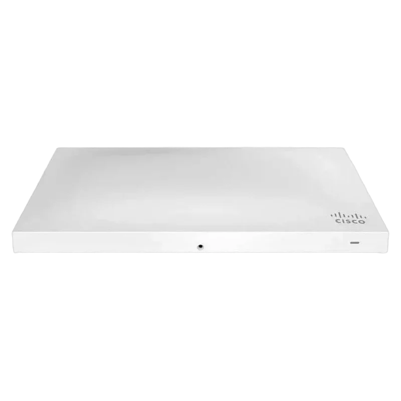
The RF performance data shows that the MR53 supports a wide range of modulation and coding rates. Representative published values include:
| Band and mode | Data rate or MCS | TX power | RX sensitivity |
|---|---|---|---|
| 2.4 GHz 802.11b | 1 Mbps | 19 dBm | -98 dBm |
| 2.4 GHz 802.11b | 11 Mbps | 19 dBm | -87 dBm |
| 2.4 GHz 802.11g | 54 Mbps | 17 dBm | -75 dBm |
| 2.4 GHz 802.11n HT20 | MCS0/8/16 | 19/22/23/27 dBm | -92/-95/-96/-98 dBm |
| 5 GHz 802.11a | 6 Mbps | 20 dBm | -91 dBm |
| 5 GHz 802.11a | 54 Mbps | 18 dBm | -74 dBm |
| 5 GHz 802.11n HT40 | MCS0/8/16 | 20/23/24 dBm | -88/-91/-92 dBm |
| 5 GHz 802.11ac VHT80 | MCS0/0/0/0 | 20/23/24/26 dBm | -85/-88/-89/-91 dBm |
| 5 GHz 802.11ac VHT80 | MCS9/9/9/9 | 15/18/19/21 dBm | -59/-62/-63/-65 dBm |
The RF table lists transmit power and receive sensitivity as multiple values for the spatial stream combinations associated with each MCS grouping. These figures are engineering reference values and should not replace a site survey or validation survey.
Presales sizing rules
- Size for required airtime and client concurrency, not the aggregate PHY rate.
- Treat 80 MHz operation as a capacity option that consumes more spectrum and may reduce channel reuse.
- Use 5 GHz as the primary service band for high-throughput clients where client support and regulatory availability permit.
- Validate 2.4 GHz channel reuse in environments with large numbers of legacy or low-bandwidth devices.
- Include voice and video traffic in the capacity model rather than relying only on maximum data rates.
- Confirm that the access switch and cabling support the required uplink speed.
- Use the dedicated scanning radio as a security and RF capability, not as additional client throughput.
- Verify country-specific frequency restrictions before final channel planning.
MR53 Uplink, Power, and Cabling
The MR53 provides two RJ45 interfaces:
- One 100/1000/2.5G BASE-T Ethernet interface
- One 10/100/1000 BASE-T Ethernet interface
The 2.5G-capable interface is the appropriate uplink for preserving additional wired capacity for the high-performance wireless configuration. A 1 Gbps connection can still provide service, but it may become a bottleneck when many clients generate simultaneous traffic or when high-rate 5 GHz service is heavily utilized.
Power options are:
- Power over Ethernet from 37 to 57 V
- IEEE 802.3at required for full operation
- Functionality-restricted IEEE 802.3af mode supported
- Alternative 12 V DC input
- Maximum power consumption of 21 W when using 802.3at
The PoE injector and DC adapter are sold separately. For new installations, the PoE design should use 802.3at-capable switching or the specified Meraki multigigabit 802.3at injector. A presales bill of materials should not assume that the access point includes a power injector or AC adapter.
The switch design should verify:
- 802.3at availability on every MR53 access port
- Sufficient switch PoE budget for the planned number of access points
- Multigigabit support where the wireless capacity model requires it
- Correct VLAN trunking and management reachability
- Cabling suitable for the selected Ethernet speed
- Availability of DHCP and upstream access to the Meraki cloud
MR53 Management and Operational Model
The MR53 is configured and managed through the Meraki cloud using a browser-based interface. The access point is self-configuring after connection to the network. It retrieves its configuration, joins the assigned network, and obtains firmware updates through the cloud.
Operational capabilities include:
- Centralized configuration
- Real-time monitoring and alerting
- Remote troubleshooting and diagnostics
- Automatic firmware updates
- Remote deployment to locations without on-site IT staff
- Usage analytics at network, device, and application levels
- API access to raw analytics data
The cloud management model reduces the need for local controllers and manual software distribution. It also makes WAN reachability and cloud access a design dependency. Management VLANs, firewall policies, DNS, DHCP, and outbound connectivity must be validated before installation.
MR53 Security, Access Control, and Compliance
The MR53 includes an integrated Layer 7 firewall with mobile device policy management. Security and access features include:
- WEP
- WPA
- WPA2-PSK
- WPA2-Enterprise with 802.1X
- AES hardware-based encryption
- TKIP
- EAP-TLS
- EAP-TTLS
- EAP-MSCHAPv2
- EAP-SIM
- VLAN tagging using 802.1Q
- IPsec VPN tunneling
- Guest device isolation
- PCI compliance reporting
- Real-time WIDS/WIPS
- Automatic rogue AP containment through Air Marshal
- Cisco ISE integration for guest access and BYOD posturing
- EMM and MDM integration
WPA2-Enterprise deployments require planning for the authentication infrastructure, certificate lifecycle, identity services, and client supplicant configuration. EAP-TLS is available where certificate-based authentication is required.
Guest access can be configured with device isolation and Internet-only access. Application-aware policies can be applied per network, SSID, user group, or individual user. Layer 7 inspection supports traffic identification and shaping so that business-critical applications can receive priority while recreational or nonessential traffic can be limited.
PCI compliance reporting assists with checking network settings against PCI requirements, but it does not by itself establish compliance for the complete solution or business environment.
MR53 Quality of Service and Mobility
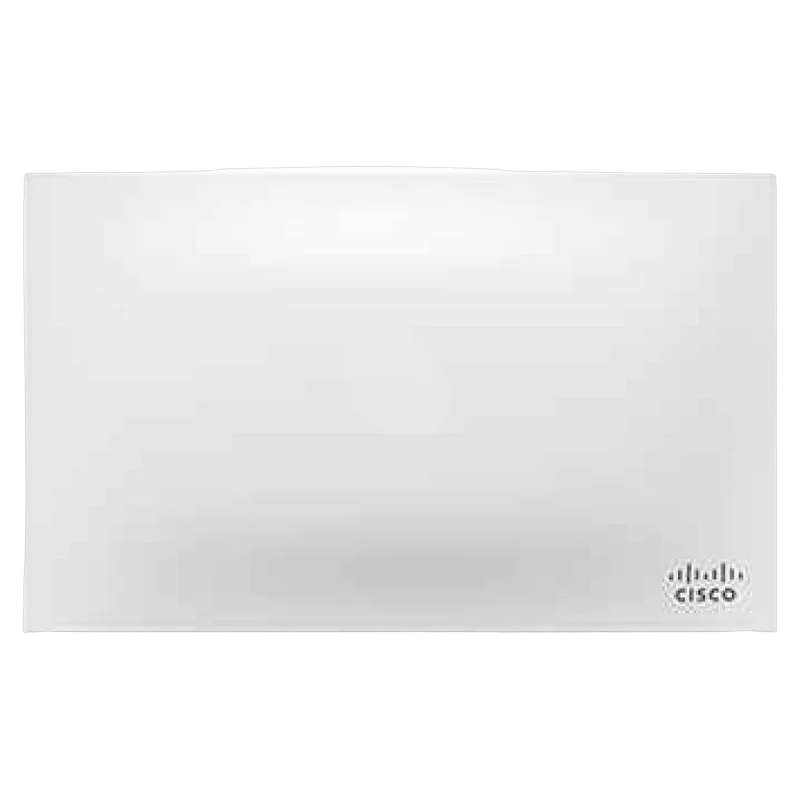
The MR53 supports wireless voice and video requirements through:
- WMM access categories
- DSCP support
- IEEE 802.1p support
- U-APSD
- Layer 7 application identification and shaping
U-APSD helps reduce battery drain on wireless VoIP phones. DSCP and 802.1p allow traffic marking and prioritization to be carried consistently across the wired and wireless network.
Mobility features include:
- PMK caching
- Opportunistic Key Caching
- IEEE 802.11r fast Layer 2 roaming
- Distributed Layer 3 roaming
- Centralized Layer 3 roaming
Roaming performance still depends on client behavior, WLAN security configuration, RF overlap, VLAN design, and application tolerance for interruption. Voice deployments should validate roaming with the actual handset models and call-control applications.
MR53 Physical, Environmental, and Installation Specifications
The MR53 has a low-profile enclosure suitable for office and commercial environments.
| Specification | Value |
|---|---|
| Dimensions | 10.56 x 6.38 x 1.58 inches |
| Metric dimensions | 268.2 x 162.0 x 38.8 mm |
| Weight | 29.6 oz, 840 g |
| Operating temperature | 32 to 104 degrees F, 0 to 40 degrees C |
| Operating humidity | 5 to 95 percent, non-condensing |
| Antenna type | Integrated omnidirectional |
| 2.4 GHz antenna gain | 5.5 dBi |
| 5 GHz antenna gain | 6.2 dBi |
| DC connector | 5.5 mm x 2.5 mm, center positive |
The published dimensions exclude desktop mounting feet and the mount plate. The access point supports desktop, ceiling, and wall mounting. Included mounting hardware supports ceiling tile rails sized 9/16, 15/16, and 1 1/2 inches, with flush or recessed rail options, as well as assorted cable junction boxes.
Installation features include:
- Bubble level on the mounting cradle for horizontal wall alignment
- Two included security screw options
- Kensington lock hard point
- Concealed mount plate
- Anti-tamper cable bay
The temperature and humidity limits apply to operation. The datasheet does not specify storage temperature, storage humidity, ingress protection, outdoor operation, or hazardous-location certification. The MR53 should therefore be planned for controlled indoor environments within the published operating range.
MTBF
A mean time between failures value is not specified in the provided MR53 specifications. MTBF should not be inserted into a reliability calculation, service-level commitment, or lifecycle model unless supplied through a separate authoritative source.
Acoustic noise
An acoustic noise rating is not specified. The MR53 is an access point with no published fan or sound-level specification in the provided material. Acoustic suitability for quiet rooms, recording spaces, patient areas, or other noise-sensitive locations should be validated as part of the physical deployment review rather than inferred from the enclosure design.
MR53 Standards and Regulatory Approvals
Listed IEEE standards include:
- 802.11a
- 802.11b
- 802.11g
- 802.11n
- 802.11ac
- 802.11e
- 802.11h
- 802.11i
- 802.11k
- 802.11r
- 802.11u
Safety approvals include UL 60950-1, CAN/CSA-C22.2 No. 60950-1, IEC 60950-1, EN 60950-1, and UL 2043 plenum rating.
Radio, EMI, and exposure approvals are listed for multiple regions, including the United States, Canada, Europe, Australia and New Zealand, Mexico, Taiwan, and Japan. Country-specific restrictions apply to supported frequency bands and channel availability.
MR53 Ordering Matrix
| SKU | Description | Power or accessory role | Best For |
|---|---|---|---|
| MR53-HW | Meraki MR53 cloud-managed 802.11ac access point | Access point hardware | High-density indoor WLAN deployments requiring 4×4:4 client radios, dedicated WIDS/WIPS, BLE, and multigigabit uplink capability |
| MA-PWR-30W-XX | Meraki AC adapter for MR Series; XX denotes US, EU, UK, or AU variant | 12 V DC power option | Sites using local DC power where PoE is unavailable or not selected |
| MA-INJ-5-XX | Meraki multigigabit 802.3at PoE injector; XX denotes US, EU, UK, or AU variant | 802.3at PoE power injector | Single-AP or retrofit installations requiring multigigabit PoE without an 802.3at switch port |
A Meraki access point license is required. The license is separate from the hardware SKUs shown above.
MR53 Warranty and Service
The MR53 is specified with a lifetime hardware warranty that includes advanced replacement. The warranty covers the hardware under the terms of the applicable service policy. It does not remove the requirement for a valid Meraki access point license, suitable power infrastructure, correct installation, or a supported operating environment.
For procurement and service planning, include:
- MR53-HW hardware
- An 802.3at PoE switch port or MA-INJ-5-XX injector
- MA-PWR-30W-XX only where DC powering is required
- Required Meraki access point licensing
- Mounting and security hardware verification
- Switch, cabling, DHCP, DNS, and cloud connectivity validation
The warranty and advanced replacement provision should be considered alongside operational spares, site access procedures, and the customer response model for distributed locations.