
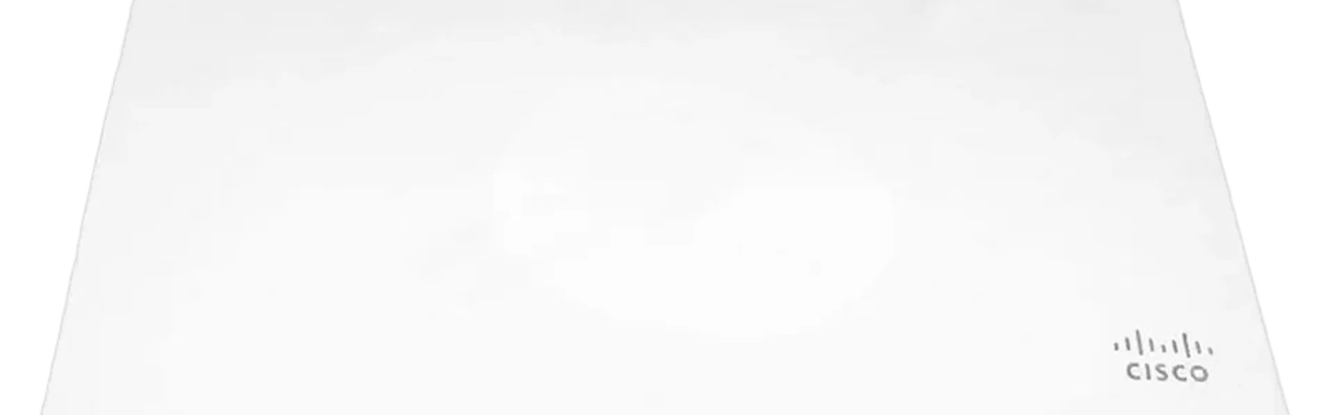
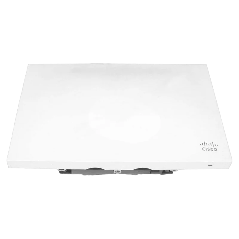
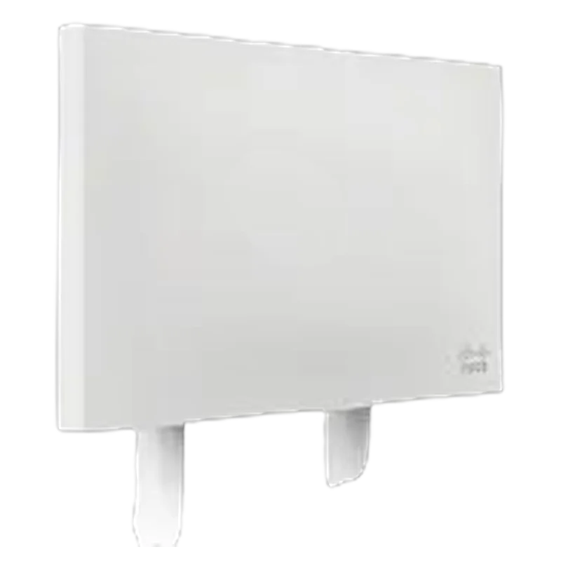
The Cisco Meraki MR84 is a four-radio, cloud-managed 4×4 MU-MIMO 802.11ac Wave 2 access point for demanding indoor and outdoor wireless deployments. It combines two client-access radios, a dedicated dual-band wireless security and RF analytics radio, and a dedicated Bluetooth Low Energy radio. The unit supports a maximum aggregate dual-radio frame rate of up to 2.5 Gbps, with a 5 GHz maximum data rate of up to 1,733 Mbps and a 2.4 GHz maximum data rate of up to 800 Mbps.
MR84 Product Positioning
The MR84 is intended for high-density environments, difficult RF conditions, industrial spaces, outdoor campuses, and deployments where continuous wireless security monitoring is required without taking capacity away from client access radios.
Primary deployment environments include:
- Outdoor corporate campuses, education sites, parks, metro Wi-Fi, and other public-area coverage zones
- Industrial facilities, warehouses, auditoriums, event centers, and large open indoor areas
- Locations requiring wireless access for scanners, security cameras, point-of-sale devices, tablets, laptops, and voice clients
- Point-to-multipoint mesh deployments where cable drops are unavailable
- Point-to-point wireless bridges between networks
- Hotspot extension using mesh while continuing to serve local wireless clients
- High-density environments supporting latency-sensitive voice and high-definition video
The MR84 uses external antennas and includes four external N-type female antenna connectors. This allows the antenna pattern to be matched to the site, including omnidirectional, patch, and sector coverage requirements.
MR84 Radio Architecture and Wireless Capacity
The MR84 operates four radios concurrently:
| Radio | Function | Key capability |
|---|---|---|
| 2.4 GHz client radio | 802.11b/g/n client access | 4×4 MIMO, four spatial streams |
| 5 GHz client radio | 802.11a/n/ac client access | 4×4 MIMO, 802.11ac Wave 2 |
| Dual-band scanning radio | WIDS/WIPS, spectrum analysis, location analytics | Continuous independent RF monitoring |
| 2.4 GHz BLE radio | Bluetooth Beacon and device scanning | BLE location-aware applications |
The dedicated third radio is significant for presales sizing. Wireless intrusion detection and prevention, spectrum analysis, rogue access-point containment, and location tracking do not need to compete with normal client traffic for airtime on the two client-access radios. The MR84 can therefore perform security and RF analysis continuously while maintaining client service.
The fourth radio provides BLE Beacon and scanning support. The datasheet identifies support for BLE visibility, device tracking, location-aware applications, and Beacon functionality. BLE capability is integrated into the access point and does not require a separate BLE access device for the stated functions.
The client radios provide:
- 4×4 MIMO with four spatial streams
- SU-MIMO and MU-MIMO
- Maximal ratio combining
- Transmit beamforming
- Packet aggregation
- Up to 256-QAM on both 2.4 GHz and 5 GHz
- Concurrent 2.4 GHz and 5 GHz operation
- 802.11n channel widths of 20 MHz and 40 MHz
- 802.11ac channel widths of 20 MHz, 40 MHz, 80 MHz, 160 MHz, and 80 + 80 MHz
The maximum advertised aggregate frame rate is a physical-layer capability and must not be treated as guaranteed application throughput. Actual throughput depends on channel width, client capability, spatial-stream support, protocol overhead, RF interference, contention, regulatory limits, antenna selection, uplink capacity, and the number and type of active clients.
MR84 Frequency Bands and RF Planning
The supported frequency ranges are:
- 2.412-2.484 GHz
- 5.150-5.250 GHz, UNII-1
- 5.250-5.350 GHz, UNII-2
- 5.470-5.600 GHz and 5.660-5.725 GHz, UNII-2e
- 5.725-5.825 GHz, UNII-3
Country-specific restrictions apply. Channel availability, transmit power, DFS operation, antenna gain limitations, and permitted channel widths must be validated for the installation country.
The 2.4 GHz client radio supports 802.11b/g/n. The 5 GHz client radio supports 802.11a/n/ac. The data sheet identifies 160 MHz support on the 5 GHz radio and a 40 MHz capability on the 2.4 GHz radio in the aggregate-rate description.
Selected radio performance values include:
| Band and mode | Data rate or MCS | Transmit power | Receive sensitivity |
|---|---|---|---|
| 2.4 GHz 802.11b | 1 Mbps | 19 dBm | -96.5 dBm |
| 2.4 GHz 802.11b | 11 Mbps | 19 dBm | -85.5 dBm |
| 2.4 GHz 802.11g | 54 Mbps | 17 dBm | -73.5 dBm |
| 2.4 GHz 802.11n HT20 | MCS0/8/16/24 | 19/22/23/27 dBm | -90.5/-93.5/-94.5/-96.5 dBm |
| 5 GHz 802.11a | 6 Mbps | 20 dBm | -90 dBm |
| 5 GHz 802.11a | 54 Mbps | 17 dBm | -73 dBm |
| 5 GHz 802.11n HT40 | MCS0/8/16/24 | 20/23/24/26 dBm | -87.5/-90.5/-91.5/-93.5 dBm |
| 5 GHz 802.11ac VHT20 | MCS0/0/0/0 | 20/23/24/26 dBm | -90/-93/-94/-96 dBm |
| 5 GHz 802.11ac VHT20 | MCS9/9/9/9 | 15/18/19/21 dBm | -61/-64/-65/-67 dBm |
The complete transmit and receive tables include 2.4 GHz 802.11b, 802.11g, and 802.11n HT20 values, plus 5 GHz 802.11a, 802.11n HT20, 802.11n HT40, and 802.11ac VHT20 values. Values are presented by MCS grouping and spatial-stream configuration.
RF design rules
- Use a site survey for high-density, industrial, outdoor, and voice deployments.
- Treat 5 GHz as the primary capacity band where client support permits.
- Do not size the network from the 2.5 Gbps aggregate frame-rate figure alone.
- Validate antenna orientation, polarization, mounting height, obstruction losses, and cable losses.
- Confirm the local regulatory domain before committing to channel plans or 160 MHz operation.
- Use narrower channels where channel reuse and interference control are more important than peak single-client rate.
- Validate roaming requirements for voice, scanners, and mobile operational devices.
- Consider the dedicated security radio when comparing the MR84 with designs that use the same radio for both scanning and client service.
MR84 Antenna and Mounting Design
The MR84 has four external N-type female antenna connectors. Supported antenna options listed for the platform include:
- Dual-band omnidirectional antennas
- Dual-band patch antennas
- Dual-band sector antennas
- A dual-band, four-port, 30-degree beam antenna
The access point mounts to walls and vertical poles. Mounting hardware is included. A security screw and concealed mount plate are provided for physical protection and installation control.
Antenna selection should follow the coverage objective:
- Use omnidirectional antennas for broad area coverage around a pole or central mounting location.
- Use patch antennas for directed coverage through corridors, across open areas, or toward defined client zones.
- Use sector antennas for outdoor perimeter, roadway, yard, campus edge, and sectorized coverage.
- Use a 30-degree beam antenna where a narrow directional pattern is required and the coverage geometry supports it.
The antenna part number AIR-ANT2513P4M-N= is listed as requiring a Meraki Enterprise license, with instructions to contact Cisco directly for that antenna. The data sheet does not provide antenna gain, cable specifications, or maximum permissible cable length; these items must be included in detailed RF engineering.
MR84 Ethernet, Uplink, and PoE
The MR84 provides two RJ45 Ethernet interfaces:
- One 100/1000/2.5G BASE-T Ethernet port
- One 10/100/1000 BASE-T Ethernet port
The multigigabit interface supports the uplink capacity required by the high-performance 802.11ac Wave 2 radio configuration. The two Ethernet ports can also be configured for link aggregation when the switching infrastructure does not support multigigabit Ethernet.
When the second Ethernet interface is not used for link aggregation, it can connect a wired client device, such as a security camera.
Power requirements are:
- Input range: 37-57 V
- 802.3at required for full functionality
- 802.3af supported in a functionality-restricted mode
- Maximum power consumption: 21 W using 802.3at
- PoE injector sold separately
PoE presales rules
- Specify an 802.3at-capable switch port or the separately listed multigigabit 802.3at injector for full functionality.
- Do not design a full-capability deployment around 802.3af.
- Confirm the switch power budget for every access point, particularly in large outdoor or high-density rollouts.
- Validate that the switch port supports the required Ethernet speed and the applicable PoE standard.
- Treat link aggregation as a switch-dependent design option; confirm switch support and configuration requirements before including it in the bill of materials.
- If a wired camera is connected to the second port, account for its traffic on the access point uplink and switching design.
MR84 Cloud Management and Operations
The MR84 is configured and managed through the Meraki Dashboard. The stated operating model is self-configuring and cloud-managed:
- The access point is connected to the network and powered.
- It connects to the Meraki cloud.
- It retrieves its configuration.
- It joins the assigned network.
- Firmware updates are delivered automatically through the cloud.
This model supports deployment across multiple sites without requiring local controller hardware or on-site IT staff at every location. Centralized monitoring provides alerts when network problems are detected. Remote diagnostic tools support troubleshooting of distributed networks.
Presales teams should verify the customer network path to the Meraki cloud, including DNS, routing, firewall policy, proxy behavior, and any outbound access controls. The data sheet describes cloud operation but does not list the required firewall ports or detailed cloud connectivity prerequisites.
MR84 Security, Segmentation, and Access Control
Security functions include:
- Integrated Layer 7 firewall
- Mobile device policy management
- Real-time WIDS/WIPS
- RF alerts and spectrum analysis
- Automatic rogue access-point containment through Air Marshal
- Guest access with device isolation
- VLAN tagging using 802.1Q
- IPsec VPN tunneling
- PCI compliance reporting
- WEP, WPA, WPA2-PSK, and WPA2-Enterprise
- 802.1X authentication
- EAP-TLS, EAP-TTLS, EAP-MSCHAPv2, and EAP-SIM
- TKIP and AES encryption
- Enterprise Mobility Management and Mobile Device Management integration
- Cisco ISE integration for guest access and BYOD posturing
The platform supports secure employee and guest access, but security architecture still requires customer-specific decisions regarding identity services, VLANs, guest egress, certificate deployment, firewall policy, and monitoring ownership.
MR84 Traffic Management, Voice, and Video
The MR84 includes Layer 7 packet inspection, classification, and traffic shaping. Policies can be applied at the:
- Network level
- SSID level
- User-group level
- Individual-user level
Traffic policies can prioritize mission-critical applications and limit recreational or nonessential traffic, including peer-to-peer and video streaming applications.
Quality-of-service functions include:
- WMM access categories
- DSCP support
- 802.1p support
- U-APSD advanced power saving
- Layer 7 application identification and shaping
Mobility functions include PMK, OKC, and 802.11r for fast Layer 2 roaming, plus distributed or centralized Layer 3 roaming.
For voice and video projects, the access point should be evaluated as one component of the end-to-end service. The wired switching path, WAN, authentication service, application servers, DSCP trust boundaries, RF coverage, channel reuse, and client device behavior must all be validated.
MR84 Analytics and Location Functions
The MR84 provides embedded location analytics reporting and device tracking. Global Layer 7 traffic analytics can be viewed per network, per device, and per application.
The data sheet also identifies visitor numbers, dwell times, repeat visit rates, trend comparison, and customizable analysis through simple APIs. These functions are relevant to retail, public venues, education, and campus environments where wireless infrastructure is also used to derive physical-space analytics.
The dedicated scanning radio supports full-time Wi-Fi location tracking and RF visibility without removing a client-access radio from service.
MR84 Environmental and Physical Specifications
The MR84 is designed for harsh environments and is tested for:
- Salt spray
- Vibration
- Extreme thermal conditions
- Shock
- Dust
The enclosure has an IP67 environmental rating.
| Specification | Value |
|---|---|
| Operating temperature | -40 F to 131 F (-40 C to 55 C) |
| Relative humidity | 5 to 95 percent, non-condensing |
| Environmental rating | IP67 |
| Dimensions including mounting bracket | 28.6 cm x 17.6 cm x 18.5 cm |
| Weight | 3.8 lb (1.7 kg) |
| Mounting | Walls and vertical poles |
| Physical security | Security screw and concealed mount plate |
The data sheet does not specify MTBF. It also does not provide an acoustic-noise rating, fan-noise value, or sound-power level. No acoustic performance should therefore be included in a silent-environment acceptance criterion without separate manufacturer documentation or site validation.
For outdoor installations, IP67 protection does not remove the need for correct cable sealing, connector protection, grounding, lightning protection, mast bonding, and compliance with local installation codes. The data sheet does not provide a lightning-protection specification.
MR84 Warranty and Service
The MR84 includes:
- One-year hardware warranty
- Advanced replacement
The data sheet does not provide additional warranty exclusions, regional service-level terms, replacement logistics, software subscription terms, or support response targets. The Meraki Enterprise license is identified as required for the AIR-ANT2513P4M-N= antenna option. Licensing requirements should therefore be checked as part of the complete solution bill of materials rather than treating the hardware SKU as the entire service entitlement.
MR84 Ordering and SKU Matrix
| SKU | Description | Best For |
|---|---|---|
| MR84-HW | Meraki MR84 Cloud Managed 802.11ac access point | Core MR84 hardware for high-density indoor, outdoor, industrial, and mesh deployments |
| MA-INJ-5-XX | Meraki multigigabit 802.3at PoE injector; XX identifies US, EU, UK, or AU variant | Sites without suitable 802.3at PoE switching or deployments requiring a local injector |
| MA-ANT-20 | Meraki dual-band omnidirectional antennas | Broad-area coverage from central or pole-mounted locations |
| MA-ANT-25 | Meraki dual-band patch antenna | Directed indoor or outdoor coverage toward a defined client area |
| MA-ANT-27 | Meraki dual-band sector antenna | Sectorized outdoor coverage such as yards, campuses, and perimeter zones |
| AIR-ANT2513P4M-N= | Dual-band, four-port, 30-degree beam antenna | Narrow directional coverage where a 30-degree beam is appropriate; contact Cisco directly and verify the required Meraki Enterprise license |
The MR84-HW does not include the PoE injector or antenna options shown separately in the ordering information. The final bill of materials must therefore include the selected antenna, an appropriate PoE source, mounting requirements, cabling, and any required licensing.
MR84 Presales Qualification Checklist
Before quotation or design approval, confirm:
- Indoor, outdoor, industrial, or mixed deployment environment
- Required coverage area and client density
- Expected client device types and spatial-stream capabilities
- Voice, video, scanner, camera, POS, or other latency-sensitive workloads
- Required antenna pattern and mounting geometry
- Country-specific frequency and channel restrictions
- Availability of 802.3at PoE
- Switch port speed and multigigabit support
- Need for link aggregation
- Use of the second Ethernet port for a wired device
- Cloud connectivity and firewall requirements
- Authentication method and identity-platform integration
- Guest isolation and VLAN architecture
- WIDS/WIPS and rogue containment policy
- Location analytics and BLE requirements
- Outdoor grounding, surge protection, and cable sealing
- Warranty and advanced-replacement expectations
- Separate antenna and injector requirements in the final SKU list